
What this part does
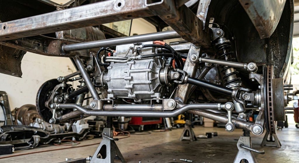
The drive unit sets the driveline centerline and load path. That means motor placement affects not only acceleration, but also axle articulation, bush or mount stress, wheel-hop tendency, thermal routing, and how easy the unit will be to remove later.
- Core entities to understand: drive unit, subframe or cradle, half-shafts, CV joints, plunge travel, static ride height, bump and droop travel, mount compliance, cooling loop, controller or inverter integration.
- The swap is harder than it looks because a classic chassis may have narrow tunnels, old pickup geometry, limited rear structure, and poor space for cooling hardware or battery weight placement.
- A donor photo alone does not prove fitment. Packaging must be validated against the exact chassis, suspension, hubs, and planned ride height.
Common failure signs
- Vibration under acceleration or at a narrow road-speed band can point to axle angle mismatch, CV operating angle issues, or mount movement.
- Clunking on take-up or lift-off can indicate excess lash, mount shift, axle plunge limits, or interference at full torque reaction.
- Noise or harshness that changes with bump and droop can point to half-shaft geometry or contact with body, cradle, or exhaust shielding.
- Fluid seepage, torn boots, or repeated joint wear can reflect poor shaft alignment or over-travel.
- Heat soak, power reduction, or repeated fault behavior after spirited driving can suggest cooling layout or airflow problems rather than purely mechanical failure.
A symptom seen only during loaded suspension movement is more useful than a symptom found with the car lifted and wheels hanging.
Before replacing it
A cautious rule is simple: if the symptom changes with ride height, load transfer, or suspension travel, investigate geometry before replacing hard parts. If the fault appears only after heat or repeated acceleration, add cooling and integration checks before condemning the drive unit.
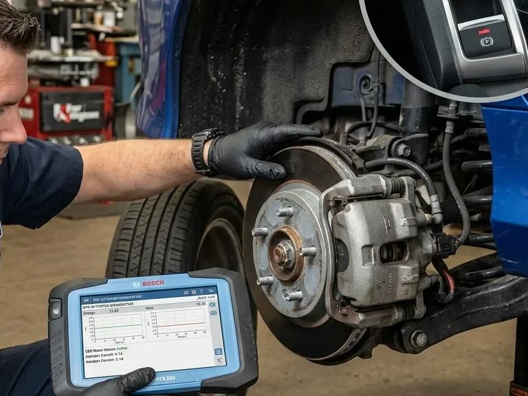
Can scan-tool faults prove the Tesla drive unit is bad after a swap?
Not by themselves. Fault behavior can reflect integration mismatch, cooling limits, sensor strategy, or controller configuration. The mechanical package and exact hardware combination need to be checked alongside any scan results.
- Inspect-first path: verify mount geometry, axle operating range, clearance through travel, and cooling flow path.
- Replace-only-if-confirmed path: condemn the drive unit only after mechanical geometry, controls, and thermal support are shown to be correct.
- Stop-work trigger: any evidence of HV insulation damage, structural cracking, or repeated axle bind under travel.
Inspection steps
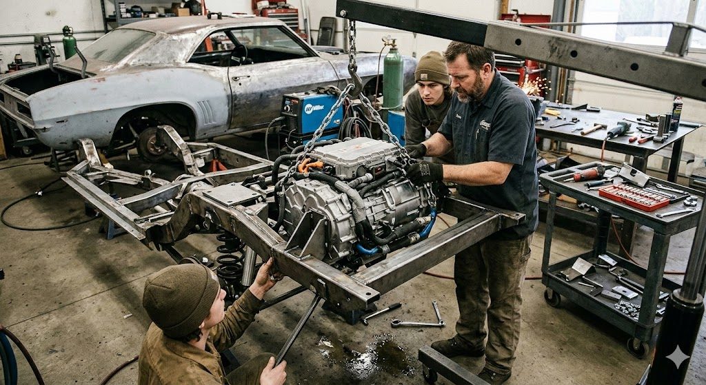
- What a Tesla drive unit retrofit actually involves
- Owner-observable signs of misalignment, stress, and interference
- Why fault behavior after installation does not automatically prove a bad drive unit
- Safe owner checks before parts replacement
- Technician checks for geometry, fabrication, cooling, and NVH
- A practical decision path for mockup, sourcing, validation, and commissioning
Owner checks you can do safely
- Set the vehicle at realistic ride height with the suspension loaded, not hanging free.
- Map hub centerlines, likely drive unit centerline, frame or trunk floor clearance, and service removal paths.
- Check where full bump and full droop would place the half-shafts, boots, and nearby structure.
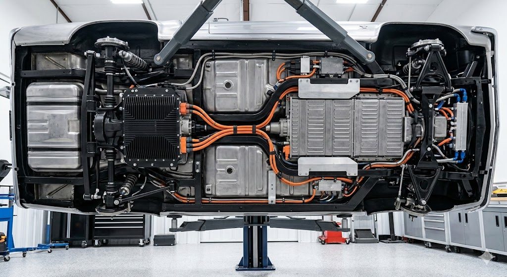
- Look for packaging conflicts with cooling lines, battery enclosure plans, rear floor, crossmembers, and brake hardware.
- Photograph and note every hard contact risk before any mount design is treated as final.
Technician checks that require measurement and fabrication
- Confirm axle working angle and plunge reserve across travel with the intended ride height and bushing compliance.
- Evaluate cradle design, mount reaction loads, weld access, reinforcement needs, and service removal strategy.
- Validate cooling hardware placement, hose protection, airflow path, and bleed strategy for the chosen system layout.
- Assess NVH transmission into the shell and whether mount stiffness trades away durability or cabin comfort.
- Buy only after the chassis has been measured at ride height and the expected axle line has been mapped.
- Confirm what is included: drive unit, mounting references, shafts if relevant, cooling ports, sensors, and any controller or interface hardware you actually plan to use.
- Inspect for impact damage, cracked housings, damaged connectors, fluid leakage, torn boots, and evidence of poor storage or corrosion.
- Ask how the unit was removed, stored, and tested, but treat sales claims as secondary to your own fitment and inspection plan.
- If the project depends on a specific inverter or control strategy, verify that exact hardware combination before purchase.
Used-part value is not only the price of the unit. Missing mounts, incorrect shafts, or an incompatible controls path can make a cheap donor the expensive option.
Replacement notes
| Likely problem source | What it can cause | Why it matters |
|---|---|---|
| Mount geometry or unit position | Vibration, bind, seal stress, mount overload | The half-shafts and mounts work through dynamic travel, not static photos. |
| Poor axle length or plunge planning | Joint wear, harshness, contact at bump or droop | A shaft that fits at ride height may still run out of travel in motion. |
| Weak cradle or structure | Clunks, alignment drift, cracking, NVH | Torque reaction can move the whole assembly even when the drive unit is sound. |
| Cooling or thermal packaging | Heat-related faults, reduced output, repeated warning behavior | A mechanically neat swap can still fail when the cooling path is undersized or badly routed. |
| Used donor condition | Noise, leakage, or internal wear | Important, but often overblamed before the chassis package is proven. |
Cooling, serviceability, and NVH deserve equal attention. If the drive unit cannot be accessed without major disassembly, or if cooling hoses run through damage-prone areas, the build may become expensive to maintain even if it drives well at first.
FAQ
Can a Tesla drive unit fit in any classic car?
No. It can fit some projects well, but viability depends on chassis width, suspension layout, axle geometry, structure, cooling space, weight distribution, and service access.
What usually causes vibration after a classic-car EV swap?
Vibration often points to axle angle mismatch, plunge problems, mount movement, or structural compliance before it proves an internal drive unit fault.
Is this a good DIY project for a first EV conversion?
Usually only if the builder stays realistic about fabrication, measurement, and high-voltage limits. A hybrid DIY-professional path is often safer and more efficient.
Do installation faults mean the donor drive unit is bad?
Not necessarily. Fault behavior can come from control integration, cooling limits, sensor issues, or packaging mistakes. Mechanical context matters.
When should I stop and involve a specialist?
Stop when you find axle bind through travel, structural cracking risk, cooling packaging conflicts you cannot resolve cleanly, or any high-voltage task outside your training and equipment.

Comments
Be the first to add a practical repair note or follow-up question.